Thursday, 29 October 2020

Basic Electronics Lesson03 Insulators,conductors and semiconductors

 Insulators,conductors and semiconductors

Hydrogen atom

A hydrogen atom has the simplest structure of all.The two video show what is the hydrogen atom and how hydrogen and other atoms iexist in nature.


Conductors
Conductors are the materials or substances which allow electricity to flow through them. They conduct electricity because they allow electrons to flow easily inside them from atom to atom. Also, conductors allow the transmission of heat or light from one source to another.

Examples of conductors include metals, aqueous solutions of salts (i.e., ionic compounds dissolved in water), graphite, and the human body. 

Many materials are used to transmit electrical energy, but those most frequently specified for types of conductors are coppercopper-covered steel, high strength copper alloys, and aluminum.

Insulators
 An insulator is a material which is a poor conductor of electricity or heat. Some common insulators include wood, plastic, glass, porcelain and Styrofoam; Styrofoam and plastic see wide use in household applications.

Semiconductors
Semiconductors are materials which have a conductivity between conductors (generally metals) and nonconductors or insulators (such as most ceramics). Semiconductors can be pure elements, such as silicon or germanium, or compounds such as gallium arsenide or cadmium selenide.

Have look at this video and you will understand why metals are conductors  of electricity.


Monday, 19 October 2020

Basic Electronics Lesson02 Voltage,Current and Resistance(Ohm's Law)

 Measurement of Voltage,Current and Resistance(Ohm's Law)


Electric charge and the coulomb

An electric current consists of  aflow of electrons.These electrons are negatively charged and are an important part of an atom.The coulomb is used to measure electric charge.The video clip below gives an illustration of this:-


Electric current and the ampere

 You may have already used a filament lamp rated at 6V,0.06A(60mA).

The ampere is used to indicate the strength of  a current,and is measured in units of coolomb per second.In other words,electric current is the rate at which electric charge in coulomb moves through acircuit.It is easy to remember that one ampere is electric charge flowing at the rate of one coulomb per second,or 1A =1 coulomb/second = 1 C/s.

The 6V ,60mA  filament lamp will give  1A is 1 coulomb per second,60 mA=0.06 colomb per second.
.The video clip below gives an illustration of this:-

The letter I is the symbol used for electric current 

What the volt  measures?

The electromotive force of battery is the electrical force between its terminal which makes current flow round a circuit connected to it.The volt is the unit for measuring e.m.f.; for example we say the emf of a battery is 9 volts.

The potential(p.d.) is the difference of electrical force,measured in volts,between the terminals of a component which makes the current flow throughthe component.The  volt is the unit of e.m.f. and p.d.and it is measured using a voltmeter which is connected in  parallel with the component through which the current flows.

Proteus diagram


Sunday, 20 September 2020

Basic Electronics Lesson1 Current

What is an alternating current?

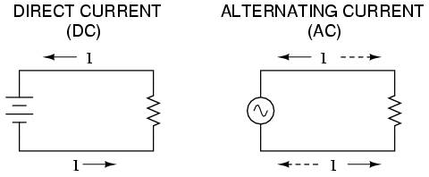
As useful and as easy to understand as DC is, it is not the only “kind” of electricity in use. Certain sources of electricity (most notably, rotary electro-mechanical generators) naturally produce voltages alternating in polarity, reversing positive and negative over time. Either as a voltage switching polarity or as a current switching direction back and forth, this “kind” of electricity is known as Alternating Current (AC): Figure  below


The dc current video


The ac current video


The following video explains the concept of dc and ac cuurent


Monday, 11 May 2020

audio preamp


Design of an Audio preamplifier using bipolar transistor

This preamplifier is based on the Sziklai bipolar transistor configuration


 Working of Sziklai Transistor Pair

Here we are demonstrating the switching test of the Sziklai pair by giving it a turn-on voltage of 0.75v. Sziklai pair starts conducting at this voltage and LED turns on, that means the turn-on base-emitter voltage for Sziklai pair is equal to normal transistor i.e. 0.75v. 


If we apply pulse input voltage at the base terminal of the NPN transistor Q1 to turn this ON, the PNP transistor Q2 is already in the forward biased state. Therefore, the current travel through the emitter of the transistor Q2 to the collector and emitter of the transistor Q1.As follows:-


 Here are few advantages of Sziklai pair:
-Sziklai pair have lower quiescent current for better linear operations.
-Thermal stability of sziklai pair is superior to the Darlington pair.
-It has faster response time than Darlington pair.
-The turn-on voltage of sziklai pair is equal to a normal transistor, while Darlington takes twice the input voltage.
In order to provide dc base bias for Q1 ;the bias voltage is set by R1 and R4 as follows:-


Sziklai Transistor Pair is arranged with the following components to act as buffer amplifier for no gain.i.e R5 2.2k and R7 2.2k as input and output port as shown.


The video below shows the preamp as unity gain  as shown with the ac voltmeter.


To get a clear idea,let us see on oscilloscope how unity gain looks like.

So as to make a reasonable audio preamplifier, the circuit is redesigned and modified as follows.

 There are two transistors(Sziklai Transistor Pair). They make up a DC feedback pair, with the negative feedback coupled from the collector of Q2 to the emitter of Q1. The input signal is applied via C3 to the base of transistor Q1. The bias voltage for this transistor is set by R1 and R4. 


The output from the first stage is taken from the collector of Q1 and its 22K load resistor R3. Q1’s output is fed to the base of Q2 and the final output signal is taken from its collector via C4. Negative feedback is applied by the 2K2 resistor R5. The 1.5nF capacitor C2 across this resistor ensures stability and reduces interference from radio frequency noise by rolling off frequencies above 48kHz. The overall gain is set by the ratio of R5 and R6. The gain equation is Gain = 1 + (2200/100) = 23 which is approximately 27 dB.

You may change R5 to adjust the overall gain if required. Keep in mind that you may need to adjust C2 as well to maintain the same high frequency roll off. For use with an electric guitar for example, you might try R5 = 10k and C2 = 470pF if there is insufficient gain with the circuit as shown. However you may prefer to leave C2 as shown to reduce noise

The capacitor C3 in series with R6 sets the lower frequency response to 72Hz. This reduces microphone proximity effect and reduces susceptibility to wind and breath noise. If you require a flatter bass response, you may increase the value of C3. A 47 uF capacitor will give a low frequency break point of approximately 33 Hz with 6 dB per octave roll off.


Specification D.C. Input : 6 – 12 V at 2 – 3 mA min.
Maximum output : ~ 2.5 V RMS with 12 V supply
Maximum input : ~ 100 mV RMS (gain = 27 dB)
 Frequency resp. : ~ 70 Hz to 45 kHz –3 dB (circuit as shown )
 THD at 1V 1kHz : < 0.1 %
S/N ratio : > 75 dBA